Data sheet acquired from Harris Semiconductor
SCHS287B - Revised January 2004
This data sheet is applicable to the CD54/74AC240, CD54ACT240, and CD54/74ACT241. The CD54/74AC241 were not acquired from
Harris Semiconductor. See SCHS244 for information on the CD74ACT240, CD74AC244, and CD74ACT244.
The CD74AC240 and CD74ACT240 are supplied in 20-lead dual-in-line
plastic packages (E suffix) and 20-lead small-outline packages (M and
M96 suffixes). The CD74AC241 is supplied in 20-lead dual-in-line plastic
packages (E suffix) and the CD74ACT241 is supplied in 20-lead
dual-in-line plastic packages (E suffix) and 20-lead small-outline
packages (M96 suffix). The CD74AC244 and CD74ACT244 are supplied
in 20-lead dual-in-line plastic packages (E suffix), 20-lead small-outline
packages (M and M96 suffixes), and 20-lead shrink small-outline
packages (SM96 suffix). These package types are operable over the
following temperature ranges: Commerical (0 to 70
5
C); Industrial (-40
to +85
5
C); and Extended Industrial/Military (-55 to + 125
5
C).
The CD54AC240 and CD54AC244 and the CD54ACT240, CD54ACT241,
and CD54ACT244 are supplied in 20-lead hermetic dual-in-line ceramic
packages (F3A suffix) and are operable over the -55 to +125
5
C
temperature range.
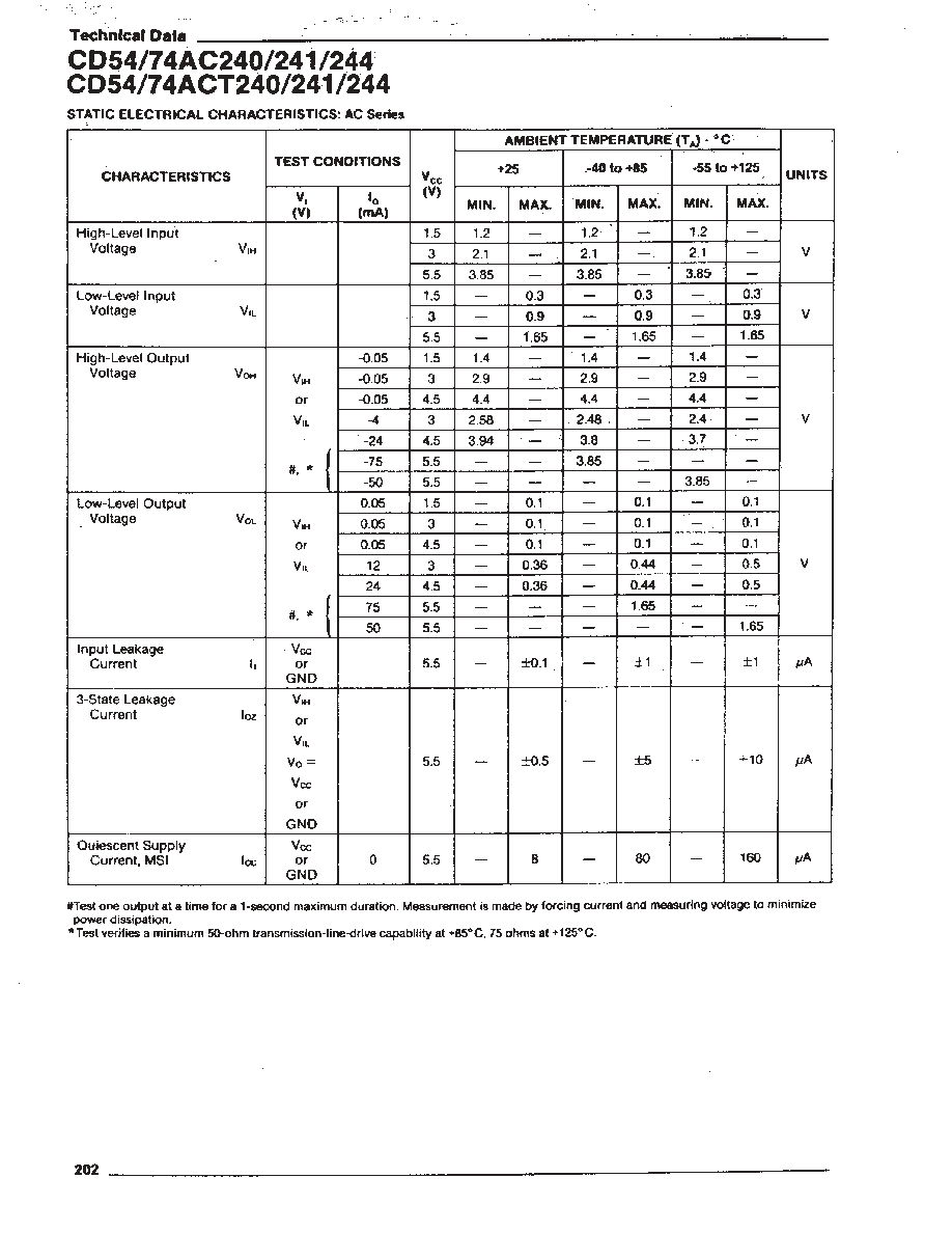
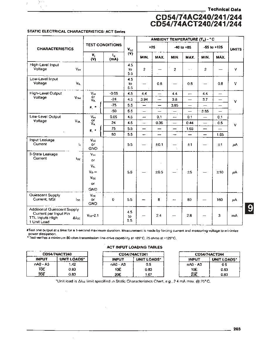
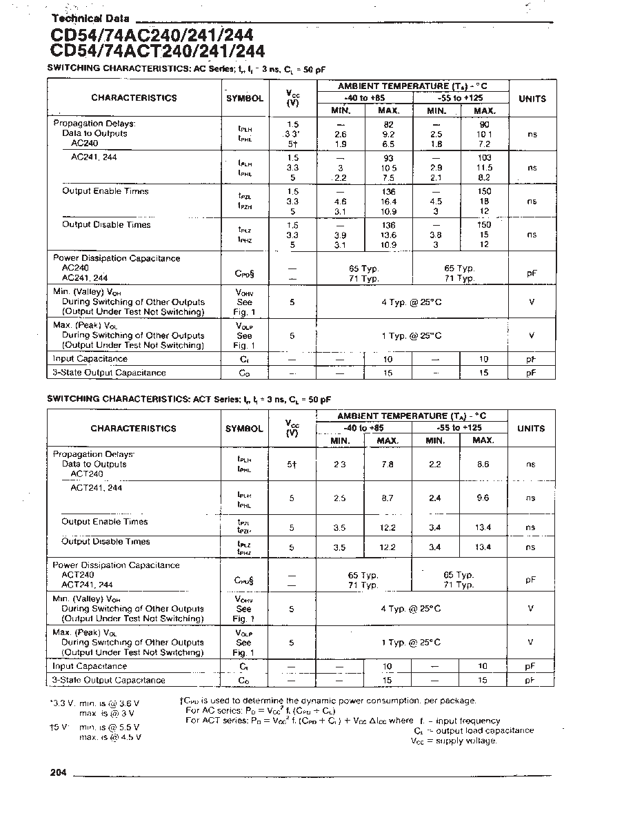
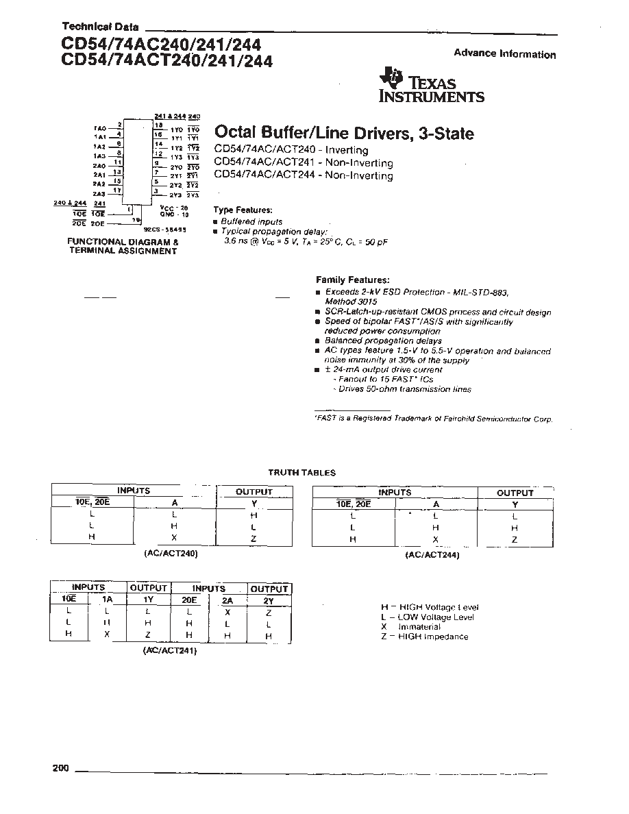
The RCA CD54/74AC240, CD54/74AC241, and CD54/74AC244 and the
CD54/74ACT240, CD54/74ACT241, and CD54/74ACT244 3-state octal
buffer/line drivers use the RCA ADVANCED CMOS technology. The
CD54/74AC/ACT240 and CD54/74AC/ACT244 have active-LOW output
enables (1OE, 2OE). The CD54/74AC/ACT241 has one active-LOW (1OE)
and one active-HIGH (2OE) output enable.
Copyright
2004, Texas Instruments Incorporated

For TA = -40 to +85
∞
C (Package Type E) . . . . . . . . . . . . . . . . . . . . . . . . . . . . . . . . . . . . . . . . . . . . . . . . . . . . . . . . . . . . . . . . . . . . 500 mW
OPERATING-TEMPERATURE RANGE (TA): CD54 . . . . . . . . . . . . . . . . . . . . . . . . . . . . . . . . . . . . . . . . . . . . . . . . . . . . . . . . . . . . . . . . . .-55 to +125
∞
C
CD74 . . . . . . . . . . . . . . . . . . . . . . . . . . . . . . . . . . . . . . . . . . . . . . . . . . . . . . . . . . . . -40 to +85
∞
C
STORAGE TEMPERATURE (Tstg) . . . . . . . . . . . . . . . . . . . . . . . . . . . . . . . . . . . . . . . . . . . . . . . . . . . . . . . . . . . . . . . . . . . . . . . . . . . . . . . -65 to +150
∞
C
LEAD TEMPERATURE (DURING SOLDERING):
At distance 1/16
±
1/32 in. (1.59
±
0.79 mm) from case for 10 s maximum. . . . . . . . . . . . . . . . . . . . . . . . . . . . . . . . . . . . . . . . . . . . . . . . . ..+265
∞
C
Unit inserted into PC board min. thickness 1/16 in. (1.59 mm) with solder contacting lead tips only. . . . . . . . . . . . . . . . . . . . . . . . . . .+300
∞
C
* For up to 4 outputs per device: add
±
25 mA for each additional output.
For TA = -40 to +70
∞
C (Package Type M) . . . . . . . . . . . . . . . . . . . . . . . . . . . . . . . . . . . . . . . . . . . . . . . . . . . . . . . . . . . . . . . . . . . . . . . . . 400 mW
For TA = +70 to +85
∞
C (Package Type M) . . . . . . . . . . . . . . . . . . . . . . . . . . . . . . . . . . . . . . . . . . . . . Derate Linearly at 6 mW/
∞
C to 310 mW
CHARACTERISTIC
LIMITS
MIN.
MAX.
UNITS
Supply-Voltage Range, VCC*:
(For TA = Full Package-Temperature Range)
AC Types
ACT Types
1.5
4.5
5.5
5.5
V
V
DC Input or Output Voltage, VI, Vo
0
VCC
V
Operating Temperature, TA
CD54
CD74
∞
C
+125
-55
-40
+85
Input Rise and Fall Slew Rate, dt/dv
at 1.5 V to 3 V (AC Types)
at 3.6 v to 5.5 V (AC Types)
at 4.5 V to 5.5 V (ACT Types)
0
0
0
50
20
10
ns/V
ns/V
ns/V
* Unless otherwise specified, all voltages are referenced to ground.